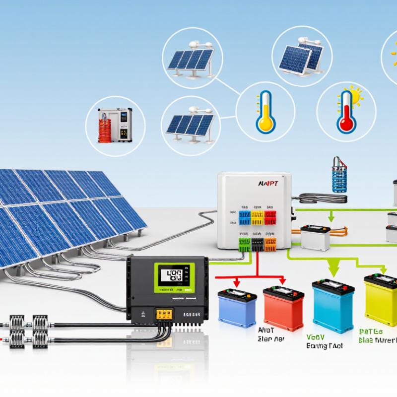
Wuxi, Jiangsu Nov 12, 2026 (Issuewire.com) - Solar MPPT Regulator Selection Trends Highlight Key Factors for Buyers
When selecting a solar MPPT regulator, buyers need to consider system safety, charging stability, and energy conversion efficiency. However, the highest advertised efficiency does not necessarily indicate the most suitable product. The regulator must match the solar panel array, battery bank, and daily energy requirements.
Several technical details deserve attention. For example, the maximum PV input voltage must be compared with the array's cold-weather open-circuit voltage (Voc), rather than its normal operating voltage. Charging current and battery compatibility are equally important. This guide explains how to compare specifications, evaluate protection functions, understand installation limits, and select a suitable regulator for different solar power systems.
A reliable selection process starts with understanding the system's panel wattage, wiring configuration, battery chemistry, and expected shading conditions. Buyers should review the manufacturer's technical data sheet and installation instructions instead of relying exclusively on product descriptions. Operating temperature, enclosure rating, cable specifications, and remote monitoring capabilities may also influence the final decision.
Define MPPT: Track the PV Array's Maximum-Power Point as Conditions Change
MPPT stands for maximum power point tracking. A solar array has a specific combination of voltage and current that produces its highest available power. This operating point changes with sunlight intensity and panel temperature.
An MPPT regulator continuously adjusts the array's operating voltage and converts the available power into a suitable battery-charging voltage. It does not generate additional energy but helps the system use the available solar power more effectively.
For example, under bright sunlight with relatively cool modules, an array operating at approximately 36 V and 8.3 A can produce around 299 W. With a battery charging voltage of 14.4 V and an assumed conversion efficiency of 97%, the estimated charging current is approximately 20.1 A.
When solar modules become hotter, their operating voltage may decrease. Under strong sunlight with hot modules, an array operating at approximately 30 V and 8.0 A produces around 240 W, corresponding to an estimated charging current of 16.2 A at 14.4 V.
Cloudy conditions also affect performance. With reduced sunlight, an array operating at 34 V and 3.5 A produces approximately 119 W, resulting in an estimated charging current of 8.0 A. Similarly, partial shading may reduce output. An example array operating at 32 V and 4.2 A produces approximately 134 W, with an estimated charging current of 9.0 A.
Cold conditions require additional attention because solar panel open-circuit voltage increases as temperatures decrease. An illustrative array operating at 38 V and 7.5 A produces approximately 285 W, with an estimated charging current of 19.2 A. The cold-weather Voc must remain below the regulator's maximum PV input voltage.
These figures are illustrative estimates. Array power is calculated by multiplying Vmp by Imp, while estimated charging current assumes 97% conversion efficiency and a 14.4 V battery charging voltage. Actual performance depends on environmental conditions, equipment specifications, and installation quality.
Estimate Energy Gain: MPPT Can Yield 10–30% More Than PWM in Some Conditions
A Solar MPPT Regulator can recover energy that a PWM controller may leave unused. However, the actual improvement depends on panel characteristics, battery voltage, and environmental conditions.
For example, a solar panel operating at approximately 18 V and 5 A produces 90 W. If a PWM controller reduces the panel voltage to match a 14 V battery, a simplified estimate gives approximately 70 W. An MPPT controller operating at 90% conversion efficiency could deliver around 81 W, representing an improvement of approximately 16%.
The potential energy gain is often estimated at 10–30% under certain conditions, particularly when panel voltage is significantly higher than battery voltage. Cold, bright mornings and partially discharged batteries may create favorable operating conditions.
However, these figures should not be treated as guaranteed performance improvements. Actual panel current changes with operating voltage, and installation factors such as shading, cable length, and loose connections can reduce energy output.
Buyers should compare panel voltage, current, battery voltage, and daily watt-hour production under similar weather conditions. IEC 62891 provides procedures for measuring MPPT performance, although laboratory efficiency figures cannot fully predict the results of every installation.
Check PV Voltage: Keep Cold-Corrected Voc Below the Controller's Maximum
A solar panel's open-circuit voltage, or Voc, increases as its cells become colder. The value listed on the panel label is generally measured under standard test conditions and may not represent the voltage reached during cold weather.
Buyers should check the panel's temperature coefficient and the lowest expected temperature at the installation site. The corrected Voc should then be calculated using the manufacturer's recommended method. For panels connected in series, the corrected voltage of each panel must be added together.
The regulator's maximum PV input voltage is a strict operating limit. The calculated cold-weather array Voc must remain below this value, with an appropriate design margin.
For example, a 12V MPPT solar regulator may support a much higher PV input voltage than its battery voltage suggests. Therefore, buyers should not assume that the battery rating indicates the maximum voltage the solar panels can supply.
If the calculated array voltage approaches the regulator's maximum limit, the number of panels connected in series may need to be reduced. A qualified solar installer should review the system design when voltage margins are insufficient.
Size Charge Output: Divide Array Watts by Battery Voltage to Estimate Amps
A practical method for estimating charging current is to divide the solar array's rated power by the battery system's voltage.
For example, a 300 W solar array connected to a 12 V battery system produces an estimated charging current of approximately 25 A. When the same array is connected to a 24 V system, the estimated current decreases to approximately 12.5 A.
These figures are preliminary planning estimates rather than guaranteed operating values. MPPT conversion losses, sunlight intensity, panel temperature, and actual battery charging voltage all influence the final current.
A 20A MPPT solar regulator may be undersized for a 300 W array charging a 12 V battery because the estimated current reaches approximately 25 A. However, the same array connected to a 24 V battery system may fall within the regulator's output-current rating.
Buyers should also check the regulator's maximum PV input voltage and power limits. A suitable charging-current rating alone does not guarantee compatibility with the entire solar system.
Check PV Circuit Sizing: NEC 690.8 Uses a 1.25× Current Factor
Solar PV circuit sizing requires attention to electrical current limits and applicable installation standards. Under NEC 690.8, the relevant PV circuit current calculations use a 1.25 factor.
For example, two parallel solar strings rated at 10 A each produce a combined short-circuit current of 20 A. Applying the 1.25 factor results in a calculated current of 25 A for the relevant sizing assessment.
Buyers should record each string's short-circuit current (Isc), multiply it by the number of parallel strings, and apply the appropriate factor. The resulting value should be evaluated against the regulator's published maximum PV input current.
It is important to distinguish the PV-side input current from the battery-side charging output current. These specifications describe different parts of the system and should not be treated as interchangeable.
The maximum PV voltage must also be checked, including the increased open-circuit voltage expected during cold weather. Wiring, conductor sizing, and overcurrent protection may require additional calculations depending on the adopted NEC edition and local installation requirements.
A properly selected regulator should operate within its published voltage and current limits. Maintaining an appropriate design margin can also help accommodate temperature changes and possible future system expansion. Final circuit sizing should be reviewed by a qualified professional.
Match Battery Chemistry and Charge Settings; Check IEC 62509 Performance Guidance
A solar MPPT regulator must be compatible with the battery's chemistry and charging requirements, not just the solar panel specifications.
Buyers should review the battery manufacturer's recommended absorption, float, and maximum charging voltages. Lead-acid batteries commonly require temperature compensation, while lithium batteries generally need compatible charging profiles and battery management system (BMS) protection.
Some lithium batteries do not support equalization charging, so buyers should confirm whether this function can be disabled in the regulator settings.
IEC 62509 provides performance and functional guidance for photovoltaic battery charge controllers. When comparing products, buyers should review documented efficiency, operating limits, protection functions, and testing conditions rather than focusing exclusively on peak efficiency ratings.
Installation environments also influence equipment selection. For example, a boat solar MPPT regulator must operate reliably in conditions involving vibration, moisture, and potentially high temperatures inside confined equipment compartments.
After installation, buyers should configure the correct battery profile before connecting the solar panels. Charging voltage can be checked with a meter during the absorption stage, while electrical connections should be inspected for abnormal heating after operation.
Battery charging settings must always follow the battery manufacturer's specifications. IEC 62509 does not establish universal charging voltages for every battery type or model.
Frequently Asked QuestionsHow can I estimate a solar array's charging current?
Divide the solar array's rated power by the battery system's voltage. For example, a 300 W array connected to a 12 V battery system produces an estimated charging current of approximately 25 A.
What would the same 300 W array produce on a 24 V system?
The estimated charging current would be approximately 12.5 A, assuming the same rated array power.
Is the estimated current a guaranteed reading?
No. Actual charging current depends on conversion efficiency, sunlight intensity, panel temperature, and the battery's charging voltage.
How do I know if a regulator is large enough?
Compare the regulator's rated output current with the estimated charging current. Also verify its maximum PV input voltage, maximum PV input current, and supported solar array power.
What battery settings should I check?
Review absorption voltage, float voltage, maximum charging voltage, and temperature compensation requirements according to the battery manufacturer's instructions.
Are lithium battery settings different?
Yes. Lithium batteries generally require chemistry-specific charging profiles and compatible BMS protection. Equalization functions should be disabled when the battery manufacturer does not permit them.
What should I inspect on a boat installation?
Check the regulator's operating temperature range, enclosure protection, moisture resistance, vibration tolerance, wiring connections, and compatibility with the onboard battery system.
How can I compare regulator performance?
Review documented conversion efficiency, operating limits, protection functions, and test conditions. IEC 62509 can provide useful performance and functional guidance.
What checks are useful after installation?
Verify battery charging settings, measure charging voltage, inspect electrical connections for abnormal heating, and monitor system performance under normal operating conditions.
Conclusion
Choosing the right Solar MPPT Regulator starts with understanding how maximum power point tracking technology adjusts solar array operation as sunlight and temperature change. Compared with PWM controllers, MPPT technology may deliver 10–30% more energy under certain conditions, although actual gains depend on system configuration and environmental factors.
Before selecting a regulator, buyers should confirm that the array's cold-corrected open-circuit voltage remains below the controller's maximum PV input voltage. Charging current can be estimated by dividing array power by battery voltage, followed by checking the regulator's rated output capacity.
PV circuit sizing and electrical protection should also be evaluated according to applicable requirements, including the relevant NEC 690.8 current calculations. Finally, the controller must support the battery's chemistry and charging settings, with IEC 62509 serving as a useful performance reference.
A systematic evaluation of voltage limits, current ratings, battery compatibility, and installation conditions helps buyers select a suitable regulator and build a more reliable solar power system.
Media Contact
Jiangsu Dahui Electronic Technology Co., Ltd. info@dahuipower.com +86 0510-88995121