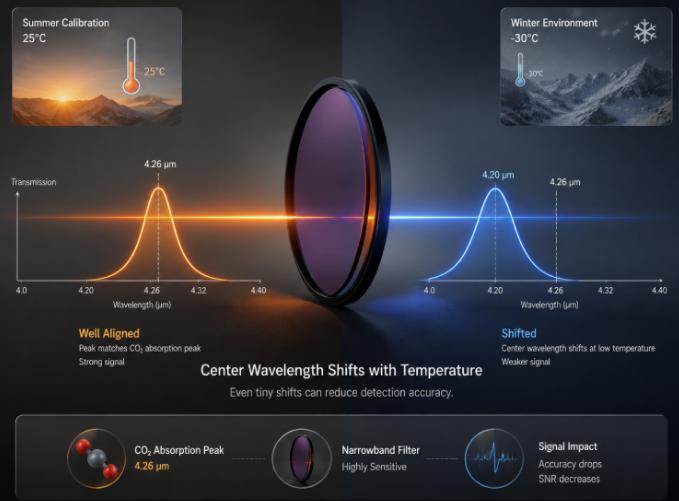
Hangzhou, Zhejiang Aug 17, 2026 (Issuewire.com) - A customer in gas detection once reported an issue: the same CO₂ analyzer, calibrated in the workshop during summer, was installed at an outdoor monitoring station in northern China in winter—and the readings started to drift. When a calibration gas was introduced, the displayed value was 2–3% lower than expected.
They checked the circuitry, the gas path, and the algorithms. Eventually, the problem traced back to the filter.
Specifically, the filter's center wavelength had shifted with temperature. Calibrated at 25°C in summer, the center wavelength was perfectly aligned with CO₂'s 4.26μm absorption peak. When the outdoor temperature dropped to –20°C or –30°C in winter—well outside the calibration conditions—the transmittance changed and the signal weakened. The difference was invisible to the naked eye, but for a narrowband filter, it was enough to take a noticeable bite out of detection accuracy.
This problem is a fundamental engineering challenge in applications sensitive to wavelength precision: infrared gas detection, infrared thermometry, and spectroscopy.
The Physical Mechanism of Temperature Drift
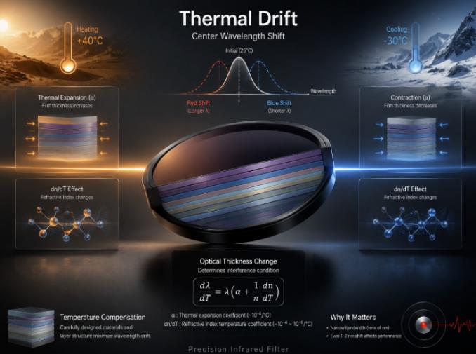
The core structure of an infrared filter is a multilayer dielectric stack—tens or even hundreds of alternating high-index and low-index layers. The optical thickness of each layer (physical thickness × refractive index) determines the interference conditions and thus the positions of the passband and stopband.
When temperature changes, two things happen simultaneously:
The coating material expands or contracts, changing its physical thickness. This effect is described by the thermal expansion coefficient α, which is typically positive and on the order of 10⁻⁶/°C.
The refractive index of the coating material changes with temperature—the dn/dT effect. This varies by material, can be positive or negative, and typically ranges from 10⁻⁴ to 10⁻⁵/°C.
The temperature drift coefficient of the center wavelength λ is correctly expressed as:
dλ/dT = λ × (α + (1/n) × dn/dT)
In other words, the direction of drift depends on the combined effect of these two terms. If dn/dT is positive and its magnitude exceeds α, the center wavelength red-shifts (moves to longer wavelengths) as temperature rises. If dn/dT is negative and its magnitude exceeds α, it blue-shifts instead—this is the design principle behind temperature-compensated filters.
How much drift is there? It depends strongly on the coating design and material selection. Different products and coating systems have significantly different thermal drift coefficients. But one thing is certain: the larger the temperature differential, the greater the cumulative drift, and the more pronounced the impact on system accuracy. For narrowband filters with bandwidths of only a few tens of nanometers, even 1–2nm of shift is not negligible.
Which Applications Are Most Sensitive to Thermal Drift?
Not all infrared applications are equally sensitive to thermal drift. Thermal imagers operate across the broad 8–14μm band—a few nanometers of filter drift is entirely imperceptible.
But for the following applications, thermal drift is a serious engineering concern:
Infrared gas detection. CO₂'s absorption peak is at 4.26μm, CO at 4.6μm, CH₄ at 3.3μm. These absorption lines are very narrow—FWHM can be just a few nanometers. The filter's passband must precisely align with the absorption peak. If it drifts, sensitivity drops and cross-interference increases.
In NDIR gas sensors, two filters are typically used: one aligned to the target gas's absorption wavelength (measurement channel), and one aligned to a nearby non-absorbing wavelength (reference channel). If the thermal drift of the two filters is mismatched, the differential signal will develop a baseline drift as temperature changes.
Infrared spectroscopy. In spectral systems that use filters for wavelength selection or pre-filtering, thermal drift directly causes wavelength calibration errors.
Laser communications and LiDAR. Narrowband filters at 905nm, 1550nm, and other bands may have bandwidths of only 1–3nm. Even a drift of 0.1–0.2nm can cause significant signal attenuation.
How Is This Addressed in Engineering?
Several common approaches:
Coating design compensation. As shown in the formula dλ/dT = λ × (α + (1/n) × dn/dT), if the coating materials have a negative dn/dT with a magnitude close to α, the two terms cancel out and thermal drift is suppressed. This is the logic behind temperature-compensated coating designs. In practice, the dn/dT of high-index and low-index materials often have opposite signs—combining them appropriately can significantly reduce the overall thermal drift coefficient. However, this increases coating complexity, and more layers come with yield and cost implications.
Substrate material selection. Silicon has a thermal expansion coefficient an order of magnitude lower than glass—filters on silicon substrates naturally have lower thermal drift than glass-based ones. Germanium is similar. In MULTI IR's infrared narrowband filter portfolio, silicon- and germanium-based models consistently outperform glass-based ones in thermal drift specifications—which is why mid-to-high-end gas detection customers tend to prefer silicon or germanium solutions.
Temperature control. Adding a TEC (thermoelectric cooler) next to the filter locks the temperature at 25°C or a fixed setpoint. This comes with trade-offs in power consumption, size, and cost—but in high-precision gas analyzers, it is standard practice.
Algorithmic compensation. Characterizing the filter's spectral data at multiple temperature points and building a temperature-wavelength lookup table in the system software for real-time correction. It's low-cost—but assumes the drift is linear and repeatable.
Passband margin design. Making the filter's passband wider than the absorption line, so that as the center wavelength drifts within a certain temperature range, the absorption peak always stays within the passband. The trade-off is reduced selectivity and potential cross-interference.
In practice, these approaches are often used in combination. For example, when MULTI IR designs solutions for gas detection customers, it typically suppresses the thermal drift coefficient to the lowest possible level at the coating design stage, then recommends simple two-point temperature compensation at the system level. Used together, the resulting readings remain stable across a wide temperature range.
A Point Often Overlooked
Thermal drift is not just a matter of "the center wavelength shifted."
Temperature changes also affect the filter's peak transmittance, passband ripple, and blocking depth.
In extreme cases, prolonged exposure to high temperature and high humidity can cause micro-cracks or interfacial diffusion in the coating layers, leading to irreversible degradation of spectral characteristics. This isn't thermal drift—this is aging.
So when selecting a filter, in addition to checking the initial spectral specifications, be sure to ask: what is the operating temperature range? What is the thermal drift coefficient? Has the product undergone high-temperature/high-humidity aging tests?
If the supplier can't answer these questions—or only provides "room temperature data"—that's a red flag.
An infrared filter may look like just a small piece of glass. But there's far more to it than meets the eye.
MULTI IR – National-level "Little Giant" Specialized and Sophisticated Enterprise. Over 10,000 types of infrared sensitive components in stock. Top 3 globally in comprehensive strength. Product portfolio covers infrared filters, optical coatings, infrared sensors, and other core categories. Lead drafter of the infrared filter industry standard.
Website: www.mirhz.com | Global Site: www.miroptech.com
Media Contact
HANGZHOU MULTI IR TECHNOLOGY CO., LTD. multi-ir@mirhz.com 86-0571-86769050