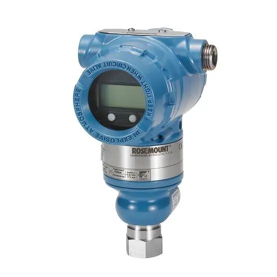
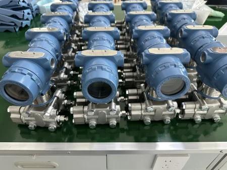
Shenzhen, Guangdong Nov 2, 2026 (Issuewire.com) - Building automation that cannot read pressure is flying blind on the half of its energy bill that moves through pipes. Chilled water, condenser water, steam and compressed air all carry their state in pressure, and the 4-20mA pressure transmitter is the device that turns that state into a number the controller can act on. This note is written for the application engineer specifying transmitters for an AHU, a chiller plant or a boiler room, and it covers why the 4-20mA loop still wins in a mechanical space, which HVAC duties actually need pressure, and how to size, install and calibrate the transmitter so the BMS reads truth instead of noise.
Why 4-20mA survives in a mechanical plant
Voltage signals die in buildings. A 0-10V pressure signal running through a plant room shares conduit with variable-frequency-drive cables, contactor coils and pump motors, and the induced noise shows up as a jittery reading that the control loop then “corrects” into instability. The 4-20mA current loop ignores that noise, because the information is carried in current, not voltage, and a current loop rejects induced voltage along the run. A 250-ohm shunt at the controller converts the 4-20mA to 1-10V for the analog input, but the field leg stays current and clean.
The other reason the loop persists is the live zero. At 4 mA the loop is alive but reading minimum, so a reading that drops to 0 mA means the wire is broken, the supply is down, or the transmitter has failed — not that the pressure is zero. In a building where a stuck “zero pressure” reading on a boiler feed line could mask a lost prime, that distinction is the difference between a nuisance alarm and a dry-run catastrophe. Voltage signals give you no such tell; 0 V is ambiguous between “no pressure” and “no signal,” and the controller cannot tell which.
The HVAC duties that actually need pressure
Not every HVAC point needs a transmitter, and over-instrumenting a plant wastes both capital and the engineer’s commissioning time. The duties that earn one are the ones where pressure drives a control decision or proves a fault. Chilled-water and condenser-water pump discharge and suction pressures set the differential that the variable-speed drive uses to hold a flow setpoint without throttling valves. Cooling-tower basin and sump levels are inferred from hydrostatic pressure when the well is not accessible. Boiler feed and steam-header pressures close the combustion and feedwater loops. And the single most common pressure point in a commercial building is the differential across a filter bank or a coil — when that ∆P climbs past a threshold, the media is loaded and the fan is working harder than it should.
Air side matters too, though it is often handled by a different sensor class. Duct static pressure, measured with a pitot or a averaging flow station, holds the VAV system stable; the transmitter there sees inches of water column, not psi, and the range is the whole game. Compressed-air mains in a campus plant are another pressure point where leaks show up first as a falling header pressure before they show up as a utility bill. A transmitter on each of these lets the building run the plant instead of guessing at it.
Gauge, absolute and differential in one building
Three reference frames appear in a single mechanical room, and confusing them is the fastest way to a reading that is wrong by a bar. Gauge pressure reads against the local atmosphere, which is what a pump discharge gauge and a filter ∆P both use — neither cares about the weather outside. Absolute pressure reads against vacuum, which matters for steam condensers and for any vacuum deaerator where the process runs below atmospheric. Differential pressure reads the gap between two points, which is the natural instrument for filter loading, coil fouling, and flow by orifice or pitot.
On our pressure transmitter platform the three are the same head with a different reference port and a different calibration, so a building that needs all three can standardize on one spare-parts family instead of three. The differential unit is the workhorse for HVAC: a differential pressure transmitter across a chilled-water coil tells you the coil is fouling weeks before the tenant feels a warm corner, and the same transmitter across a bag filter tells you to change media before the fan trips on overcurrent. Specifying the reference frame is the first line of the order, and getting it wrong means a transmitter that reads beautifully and means nothing.
Sizing the range: span, overpressure and the accuracy trap
The range is where most HVAC transmitter selections go wrong, and the error is almost always picking too wide a span. A transmitter rated 0-300 psi used to read a 0-15 psi filter ∆P resolves that 15 psi in the bottom twentieth of its range, and the stated ±0.5% full-scale accuracy becomes ±1.5 psi on a signal where 2 psi is the whole alarm band. The transmitter is within spec and useless at the same time. The span should sit just above the maximum operating pressure, not at a round number borrowed from a catalogue.
Overpressure rating is the second number, and it is not the same as range. A differential transmitter seeing a pump start-up transient on one side can momentarily see several times its span, and the diaphragm that survives that transient is specified by its overrange, not its calibrated span. In a building where a shutoff valve closes fast, that transient is routine. Accuracy, meanwhile, should be read as % of span for these low-range HVAC duties, not % of full-scale, because the two diverge exactly where the span is narrow. A transmitter quoted “±0.25% URL” is a different instrument from one quoted “±0.25% span,” and the HVAC engineer should ask which before comparing two quotes that look identical on paper.
Installation: the impulse line is where readings go to die
A pressure transmitter measures the pressure at its process connection, and in a building that connection is rarely at a convenient spot. The impulse line — the small-bore tubing or capillary that carries the pressure from the tap to the transmitter — is where most field errors are born. A vertical run below a chilled-water tap fills with air and reads low; a run above a steam tap fills with condensate and reads high; a horizontal run on a dirty condenser line silts up and reads stuck. The fix is routing: keep impulse lines short, keep them purged or self-draining, and keep them out of the mechanical-room floor where someone will kick them.
Condensation and air are the two enemies on opposite services. Steam and hot-water impulse legs need a condensate pot or a sealed system so the column height is stable, not a puddle that grows and shrinks with the weather. Chilled-water and air-side legs need to be air-free, because a bubble in a low-range ∆P line shifts the zero by more than the alarm band. Diaphragm seals and capillary assemblies move the measurement to the transmitter and eliminate the impulse line entirely for the nastiest services, at the cost of a slower response and a thermal zero shift the spec sheet will name. The installer who routes the impulse line before mounting the transmitter, rather than after, is the one whose commissioning graphs are flat.
Calibration against a reference, not against a hope
A transmitter leaves the bench calibrated, but a building’s transmitter should be checked against a reference at commissioning, because the install introduces errors no bench sees. The honest check is a deadweight tester or a calibrated reference gauge on the same tap, not a “it reads about right” against the BMS trend. The zero and span are set to the actual operating points the loop will defend — zero at the no-flow condition, span at the design maximum — not to the catalogue extremes, because the loop spends its life in the middle of the span and that is where it must be true.
Our 4-20mA pressure transmitter carries a zero and span adjustment and a stable reference, so the commissioning engineer can match the loop to the pump curve instead of to a number on a box. The caveat that protects the client: calibration proves the instrument at the moment of test, not the install a year later when the impulse line silts. A transmitter that drifts is diagnosed by re-checking against the reference, and a building that keeps the reference gauge is a building that can tell drift from fault. We state the calibration interval in the documentation rather than implying the unit is forever true, because the implication is a liability the client discovers at 2 a.m. during a chiller trip.
BMS integration: the 4-20mA arrives, the engineering begins
The transmitter hands the BMS a 4-20mA signal; the building then has to turn that into engineering units the operator understands. The analog input card scales the 1-10V (or reads the current directly on a 4-20mA card) and the programmer maps 4 mA to zero and 20 mA to span, but the mapping is only as good as the range the engineer entered. A common field fault is a transmitter shipped 0-100 kPa mated to a BMS point scaled 0-150 kPa, so every reading is two-thirds of truth and nobody notices until the coil fouls. The range entered in the controller must match the range on the transmitter nameplate, and that match is a commissioning checkpoint, not a formality.
Newer plants want the transmitter to speak the network instead of the loop, and our platform offers Modbus or BACnet MS/TP on the same head for those jobs, so a rooftop unit can put the pressure straight on the bus without an analog input it does not have. The loop still wins where the run is long, the noise is real, and the controller is an older DDC panel with analog inputs and nothing else. The engineer’s job is to pick the transport to the building’s actual controller, not to the brochure’s newest feature, and to document the scaling so the next technician is not reverse-engineering it during a fault.
What the transmitter actually buys the building
A pressure transmitter in an HVAC plant is an energy instrument first and a meter second. Pump sequencing on a chilled-water header, driven by real differential pressure, lets the lead pump hand off before it fights the lag pump, and that coordination is measurable on the utility meter within a season. Filter and coil ∆P trends turn reactive maintenance into scheduled maintenance: the media is changed when the pressure says it is loaded, not when the tenant complains, and the fan stops tripping on the overcurrent that a clogged bank forces. Boiler and steam-header pressure held by a transmitter instead of a mechanical switch keeps the combustion loop inside its band instead of hunting across it.
None of that shows up on the transmitter’s spec sheet, because the value is in the loop it feeds. A building that instruments its pressure points reads its plant; one that does not guesses at it and pays the difference in pump energy, fan trips and emergency callouts. The transmitter is cheap next to the energy it governs, and the 4-20mA loop is the reason the reading survives the room it sits in.
Differential pressure as the flow meter HVAC already owns
A building that puts a differential pressure transmitter across an orifice plate or a pitot averaging station has bought a flow meter without buying a second instrument. The orifice drops a known fraction of the line pressure as flow passes, and that drop follows the square-root law — flow scales with the square root of the measured ∆P — so the transmitter reads ∆P and the controller takes the root. The same head that flags a fouled coil thus also meters the water it moves, and the only added cost is the plate and the square-root block in the BMS. For a chilled-water plant where flow verification used to mean a clamp-on ultrasonic strapped on once a year, the DP transmitter turns flow from an occasional measurement into a continuous one.
The square-root relationship is also where the accuracy lives or dies. At ten percent of design flow the ∆P is one percent of span, so the flow reading — already a square root of a small number — carries the transmitter’s full error on a sliver of signal. HVAC engineers who care about low-load flow should size the orifice for the operating range, not the nameplate maximum, because an orifice sized for peak flow reads trash at part load where the plant actually runs most of the year. The transmitter is only as honest as the plate and the span in front of it, and that is a selection decision, not a calibration one.
Loop power: the 24 VDC that is never quite 24
A 2-wire, loop-powered transmitter draws its operating current from the same 4-20mA loop it reports on, which is elegant until the voltage budget runs short. The controller supplies 24 VDC, and that voltage must cover the transmitter’s own minimum operating headroom, the 1 V dropped across the 250-ohm shunt, and the resistive drop along the field cable — and the cable drop grows with distance and with the 20 mA it is carrying. A long run to a rooftop unit on 22 AWG can eat several volts, and a transmitter specified for a 12 V minimum suddenly sits at 10.5 V and drops out of range exactly when the building needs it.
The discipline is a voltage-budget line on the specification, not a hope that the panel’s 24 V reaches the roof. Our 4-20mA pressure transmitter states its minimum loop supply and its operating headroom, so the engineer can prove the run will deliver before the cable is pulled, instead of discovering the dropout during a summer peak. Four-wire and externally powered variants exist for the runs where the loop cannot carry the load, and choosing between them is a cable-length calculation, not a brand preference. The panel that labels its supply “24 VDC nominal” and forgets the drop is the panel whose rooftop sensors brown out at noon.
Response time and damping matched to the duty
A pressure transmitter’s response speed is a choice, and the wrong choice is the fast one. A chilled-water ∆P loop with a long impulse line and a large volume is mechanically slow; a transmitter set to track every microsecond of that sluggish signal will report the pipe’s resonances and the pump’s vane-pass frequency as if they were pressure, and the loop will chase noise. Damping the transmitter — averaging the signal over a settable time constant — is not hiding the truth; it is refusing to report the lie that the mechanical system cannot support.
Air-side and steam duties are the opposite: a duct static-pressure loop controlling a VAV damper needs to see the change fast enough to stay stable, and an over-damped transmitter makes the loop lazy and the zone uncomfortable. The right damping is set to the duty, not to a default, and the engineer who sets it from the pump curve and the damper response — rather than leaving it at factory default — is the one whose trends are usable. Our platform exposes the damping constant so the commissioning engineer can match it on site instead of living with a number chosen for a different building.
Temperature, thermal zero shift and the compensated sensor
Every pressure sensor drifts with temperature, because the diaphragm, the oil fill and the reference cavity all expand at their own rates, and the mismatch shows up as a zero shift that grows with the temperature swing. A transmitter on a steam line sees a hundred-degree change between idle and full fire, and an uncompensated head can move several percent of span across that swing — enough to mask a real fault or invent a false one. The compensation is built into the sensor and the firmware, and the spec sheet names the thermal zero-shift coefficient because that number, not the room-temperature accuracy, is what the field will live with.
On our pressure transmitter line the silicon piezoresistive and thin-film cells are temperature-compensated across the process range, so a chiller plant that cycles from winter shutdown to summer peak keeps its zero within the stated thermal band rather than wandering with the weather. The honest limit: compensation is finite, and a transmitter mounted where the process temperature exceeds its rated range will drift no matter how good the cell, so the process-temperature limit is a hard line, not a suggestion.
A specification checklist for the HVAC engineer
Before the order goes out, confirm the reference frame — gauge, absolute or differential — against the actual duty, because the three are not interchangeable in a control loop. Confirm the calibrated span sits just above the maximum operating pressure, not at a round catalogue number, and confirm the overpressure rating covers the start-up transient on the service. Confirm the impulse-line routing is self-draining or purged for the medium, or specify a diaphragm seal where the line would silt or freeze. Confirm the BMS point is scaled to the transmitter nameplate, not to an assumed range. And confirm the calibration reference will be on site at commissioning, because a transmitter checked against a hope reads like one.
Where to start
Our 4-20mA pressure transmitter line covers gauge, absolute and differential frames on one head platform, with diaphragm-seal and capillary options for the services where the impulse line would fail, and Modbus or BACnet for the plants that want the bus instead of the loop. For filter and coil duties the differential pressure transmitter is the unit to specify, and the whole family shares a spare-parts horizon that lets a building standardize instead of stocking three. Tell us the medium, the operating span and the controller’s input, and the contact page is where the specification conversation starts.
Media Contact
SHENZHEN LONNMETER GROUP anna@xalonn.com +86 18092114467 https://www.lonnmeter.com/